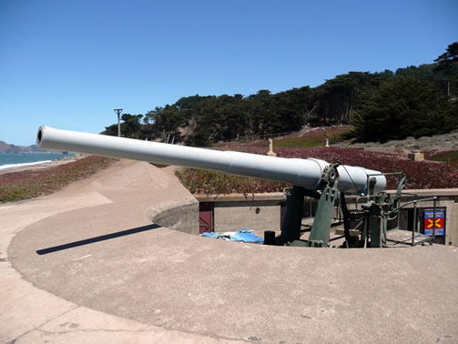
6” M1 Coastal Defense Gun
Barrel length-22’6”
Maximum effective range-13,700 to 15,800 yards
Firing rate-8 rounds per minute
Projectile weight-100lbs
The two guns were to be installed at Fort Segarra, located on the far southern end of Water Island. There are two round concrete gun emplacements one on the right and one on the left hand side of the main fort observation bunker.
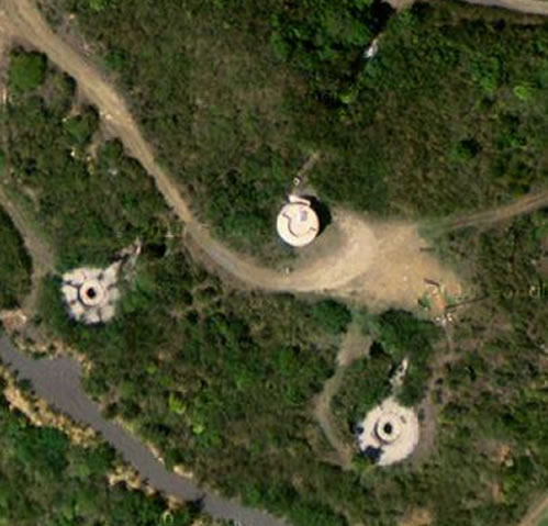
The underground central traverse magazine (‘the fort’) has a passageway that connects the two gun emplacements. The passageway has numerous rooms for the storage of ammunition and powder used by the guns. Also, rooms were set aside for generators. While on duty the gun teams and fire control supervisors stayed at the fort while other teams stayed in barracks, located elsewhere on Water Island. The passageway connects a narrow vertical staircase to another level and then up to the observation bunker with the slit opening (pill box appearing).
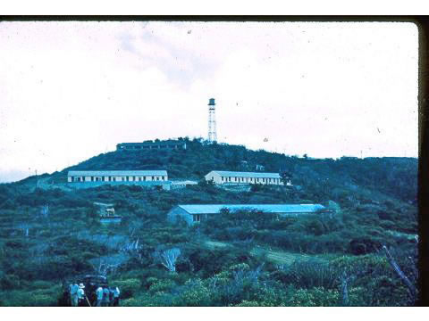
The 6” Gun teams were supported by a fire control team and a base end station. The base end station is the renovated tower at the top of Providence Hill Road and is privately owned and not open to visitors. The above photo shows there was another communications tower located in the area of Fort Segarra itself that has since been torn down.
THE FORT IS VERY DANGEROUS—DO NOT GO IN THERE ALONE. TAKE A STRONG FLASHLIGHT, AND DO NOT, DO NOT, DO NOT, GO UP THE VERTICAL STAIRCASE.
There were several variations of the 6” gun and the author is trying to get further details and will update the site when the information becomes available. While not 100% reliable, these are the specifications of the gun at this time.
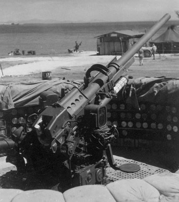
90mm Anti-Aircraft Gun
Length of gun-15’6”
Maximum effective horizontal range-12,600 yards
Gun elevation range- minus 10 degrees up to 80 degrees
Rate of Fire-15 rounds per minute
Ammunition shell weight-23.4 lbs.
Gun mounts were to be located near Druif Bay near Providence Point. Remains of one mount and its associated concrete bunkers still exists.
This gun was used extensively by the Army and Navy in WW II against aircraft and ground targets.
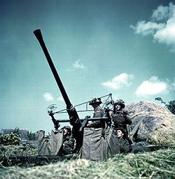
Operators could manually traverse and elevate the guns. One soldier horizontally traversed the gun to the proper azimuth (direction) while a second adjusted the vertical elevation. Ground targets were engaged using telescopic gun sights.
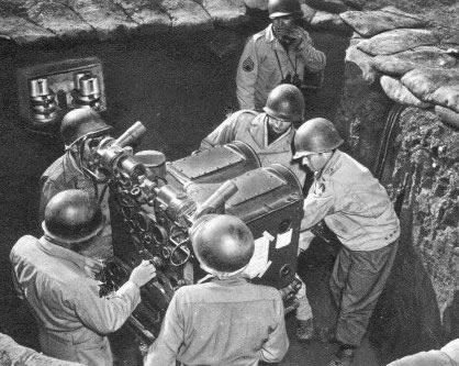
Fire direction control could also provide solutions for each gun. Visual targeting for this big gun at such long ranges was just not accurate enough. The M7 fire direction control director was essentially a mechanical computer designed to calculate firing solutions and for transmitting pointing data to the gun. The M7 also supplied flight times for the projectile so that the timed fuse on the projectile could be set to detonate at the proper point in space.
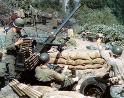
40mm Anti-Aircraft Gun
Length-7’4”
Maximum rate of fire-120 rounds per minute
Elevation-5 degrees to 90 degrees
Maximum horizontal range-3500 yards
Ammunition-high explosive for aircraft targets
-armor piercing for ground targets
Ammunition weight-2 lbs.
Maximum effective range-7.7 miles
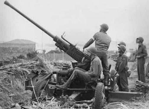
This gun was founded upon the Swedish Bofor 40mm gun which was widely used as a medium weight anti-aircraft and ground gun in WW II.
In order to supply both the Army and the Navy, ‘Chrysler’ was brought in to produce the large number of guns needed.
The Gun unit consisted of a range section and a gun section. The range section was responsible for operating the M5 director (fire control) and the power plant. The gun section manned the gun and the nearby .50 caliber machine gun.
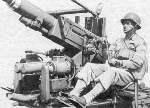
Firing was either by the fire control M5 or by line of sight. For line of sight, the gunner took a position behind the gun and would slew the gun towards the target. Under direction control the target would be tracked by the two telescopes in the M5 fire control box. Once target tracking was achieved, the gun would be remotely controlled to fire on the target.
The gun section had a total of 14 men. These were the range section range setter, elevation tracker, azimuth (direction) tracker, power plant operator, and telephone operator. The gun section included the gunner, two .50 caliber machine gun operators, the vertical gun pointer, the lateral gun pointer, an ammunition loader and firer, and two ammunition handles.
Searchlights
Typically, there were two searchlights used in tandem. The inner 24” light was to place a stationary beam to and from a barrier of light through which any unknown vessel entering the harbor had to pass. The outer 60” light was a ‘sweep light’ and ranged back and forth across the harbor.
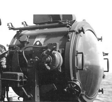
When a known vessel entered the harbor, both lights were dipped so as not to illuminate the vessel for an enemy ship. The known vessel was then trailed into the harbor by the ‘sweep light’ to ensure no enemy vessel used it as cover to enter the harbor.
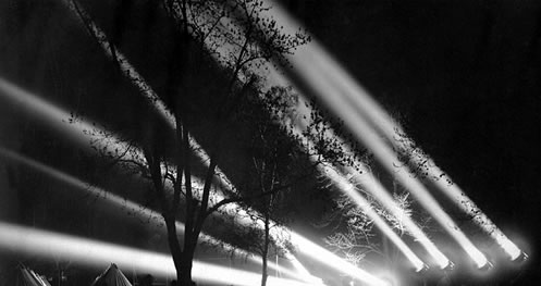
Searchlights were also used against nighttime aerial bomber raids. Pairs of searchlights were spaced a known distance apart. The triangulation was used to determine the altitude of the aircraft so that fuses of the 40mm and 90mm anti-aircraft shells could be set for maximum effect.
Made primarily by General Electric and Sperry Gyroscope in WW II, the 60” light peak output was 88M candlepower with a beam visibility of 28 to 35 miles.
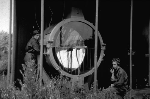
The searchlights were mounted in a concrete chamber with a semicircular “bay window” in the front. The bay window was typically fitted with sliding steel shutters to close off the opening and protect it when not in use.
Later in the war, radar was added to the mix and searchlights became even more effective. The radar and the searchlight were synchronized with the 40mm/90mm guns. The searchlight moved where the radar told it to and the guns followed the light. When the target was illuminated, the gunners would open fire.